Designing a 3D Printed Chessboard in HueForge
Yes, I've renamed it
Edit : The tiles are up on my Shopify
I'm assuming most of my readers have already seen my various social media posts with my Chessboard StageTop Tiles. If not, let me drop a small gallery here.
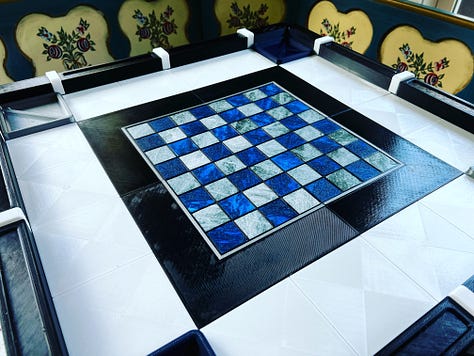
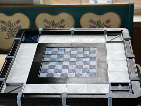
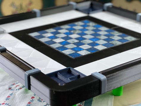
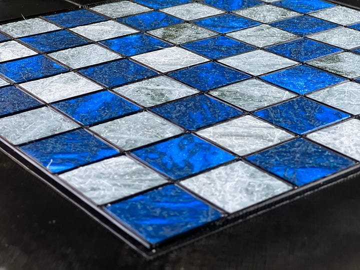
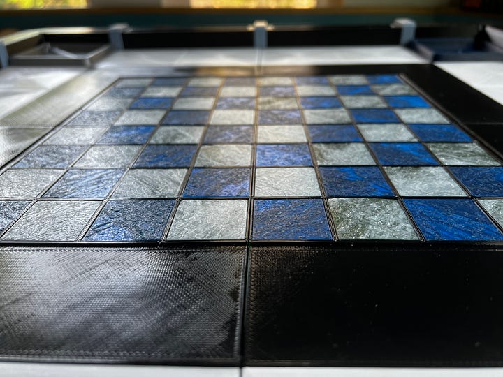
I thought it would be a good idea to walk through my process of designing these tiles in HueForge (I couldn't really keep calling it the Color Lithophane Builder).
First thing - identify that this cannot be reasonably created in a single print.
Create the board models using a traditional CAD tool.
Then create a black and white (or black and transparent) grid image. The tricky part is making sure the tiles will match your board spaces. I did this by using the same CAD software to create a DXF of the board
Then importing that into InkScape (free vector program) cleaning up any extra lines, and exporting to PNG. Make sure to set the grid to be the same size as your source image. In my case, it is 1024x1024.
I'm certain you could do this with other methods, this is the one I chose (Automated grid creation is on the future roadmap for HueForge, and will support adding a grid to a texture) .
Then I bring the saved PNG into Paint.NET (also free) and flood fill the lines with black and save the grid.
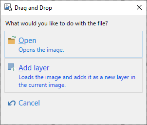
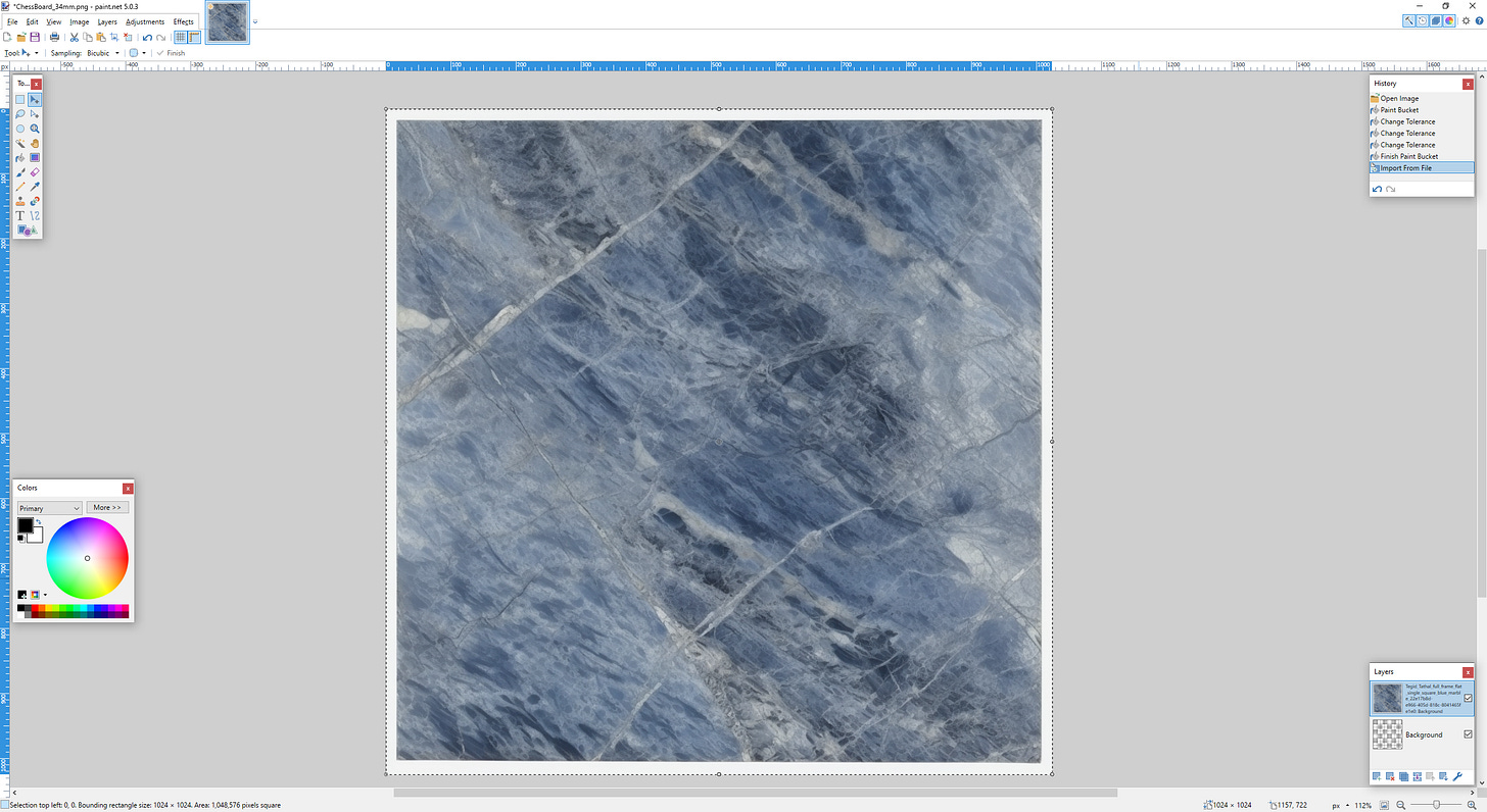
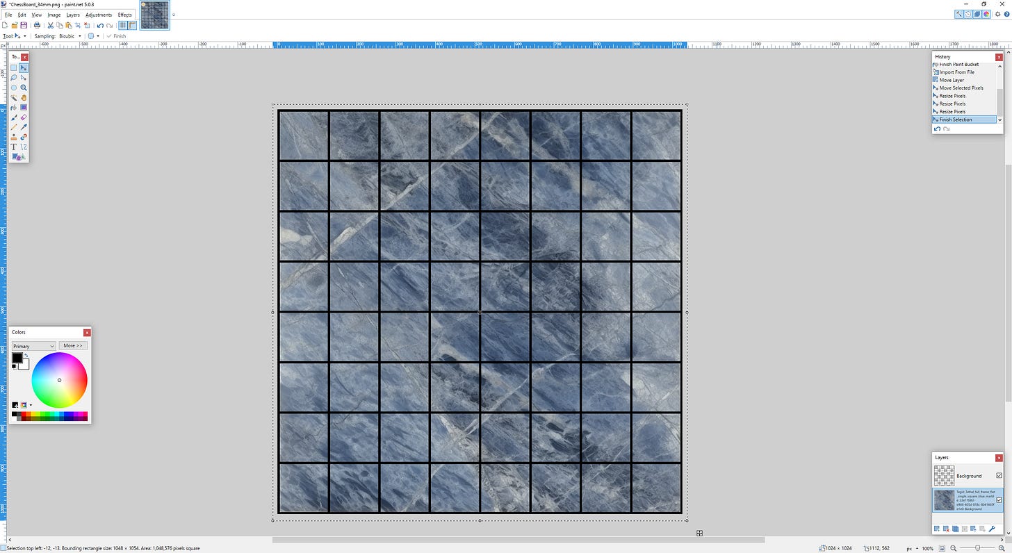
I’ve already got it loaded, so drop the image in and Add Layer
And you end up with this.
Now the marble image is on top which we don’t want, you can simply click and drag the layer down in the layer view in the bottom right.
Then with that layer selected, remove any white space by stretching the image out (Grab the circle in the middle of the edges of the original image and move them out until there is no border)
Now save as a new PNG (you already saved the grid and you don’t want to get rid of it, because you can use it as many times as you want.) It will ask you to flatten your layers which you should say yes to.
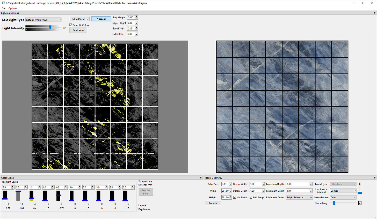
Now let's load up HueForge and drag and drop the image on top to load it. When it first comes up it will look something like this
Once it's up, click the front lit checkbox and set the layer height to 0.08 and the base layer to 0.16. Set the min depth to 0.0 and max to 1.04. After that click the No Border box.
Oops… what happened? Notice all the sliders are at the top of their ranges? When we changed all those things, they tried to stay in the right place but eventually they couldn’t and just settled on the max value. So start moving them around and changing colors as needed. Using the mouse wheel while your cursor hovers over a slider is the most precise way to adjust the sliders.
Let’s recreate a more traditional black-and-white set. With the JAYO White PETG I have, I really do get good blending, it’s more transmissive than most. Most blacks are VERY opaque. You can see that in the numbers above the sliders - white is 5 (mm) and black is 0.2. Basically 2 layers of black is pretty much opaque to light. This value is a bit more important to get exactly right in traditional lithophanes, but 1mm increments matter (just not the tenths so much). This is the section of the code under the most flux since it is the newest, so it doesn’t always end up EXACTLY as hoped for. But it does pretty well.
And yes, you will get nearly that much variation from 2 colors. That’s effectively what the tiles in the board pictured above has, it’s just dark green instead of black at the bottom. So let’s save this configuration in File→Save Project. Pick a name that is meaningful to you - I’m going to call it “Chess Board White Tiles 34mm 64 Tiles.json”
The .json is added if you don’t add it.
It actually saves 3 files. First, it makes the project, second it copies the image you used into the Projects directory and saves it with the project name. Third it saves an STL which tells us it was made with the Front Lit button checked and that it is 150x150mm in size. But that’s not the size we need. We need it to be 281x281mm, remember from above?
So let’s change that and save again (Change either height OR width and it will change the other, currently all dimensions are aspect ratio locked). Depending on your computing hardware (especially your GPU) it might make sense to work at 100x100mm or 150x150mm and only go up to your full resolution when you want to save. Also, currently 300x300mm is the maximum allowed resolution.
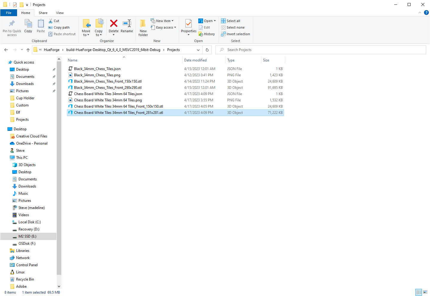
Now we need to make black tiles. The problem is, black is WAY more opaque, so it will dominate white, so we can’t just reverse the sliders.
So after playing around with options and checkboxes - something which can be rather quick, or take a long time to try and eek every ounce of performance out - I ended up with this.
A primarily black and gray tile with a little bit of gold highlights. Actually I don’t have gold filament, so maybe I’ll use copper, it should come out more or less the same. And FYI - shiny filaments have rather low transmissivity values which can be both good and bad. And you can absolutely do black, gold, black to get some cool effects, but not with every image.
So now File→Save Project as “Chess Board Black Tiles 34mm 64 Tiles.json” and since I didn’t change the board size before doing this work, it’s saved correctly at 281x281mm in size.
So now we bring one of the JSONs into your slicer. I’ve used BambuStudio, PrusaSlicer, and SuperSlicer. All will work. Cura will work too with the plugin for changes at z height.
But PrusaSlicer lets us chop the file into more manageable pieces. I have a 300x300 bed but most people don’t, so let’s divide this into quarters.
Repeat for each part
Don’t move the cursor when you cut, just rotate the plane to vertical. You’ll need to do this 3 times total.
Then save each model individually as an individually named STL. (Right Click→Export As OBJ/STL) I delete each one from the slicer as I go to make sure I don’t export the same one twice by mistake.
Once you are down to the last one, it’s time to switch to your 0.08mm profile with 100% infill and 0.16mm base layer height. If you don’t have one, you are going to want to work on one and save it off so you can get back to it easily.
Then slice it and wait. And wait. And wait. You might literally want to go make a sandwich and eat it while you wait. It’s crazy slow to slice it this way. Hopefully when it’s more than me and a couple of my friends slicing this way, the slicer makers will listen to my requests to speed this up. (I legitimately think it can be sped up if the user can inform the slicer that there are certain guarantees about the model that these files will meet). This is another reason to chop the big file into pieces, just to slice it faster. Though if you CAN print a half file at once, it’s all the pieces you need for an entire board.
EVENTUALLY
The black grid lines and the 0.0 mm minimum depth is what allows us to generate separate tiles here. Truly black grid lines become 0 height and the slicer looks at those regions and says “there is nothing there for me to print” and without having to have a ton of separate tiles, the board can be generated.
Now we need to add our filament change (these are the White tiles) so reload the project, or refer back to the image above and see that the black slider says 0.4mm or layer 4. Right click on the 0.4mm line to the right of the sliced GCODE and click the + button. If you adjust the filament color to black and the color above the change to white, you end up seeing this
It would be nice to check and make sure this matches the tool. And we can. Click on the Normal button up top next to the “Reload Shaders” button and it will change to the “slicer view”
But then since we split this into quarters, where is the section we are looking at?
Rotating the slicer (HueForge doesn’t have as many navigational commands in the view window)
And knowing this is 1/4 of the original, you can see it is the bottom left corner. While it isn’t EXACT, mostly because of nozzle width issues, it is basically the same. You can go ahead and print this!
Then repeat this process for a dark tiles, using their layer swap values and colors.
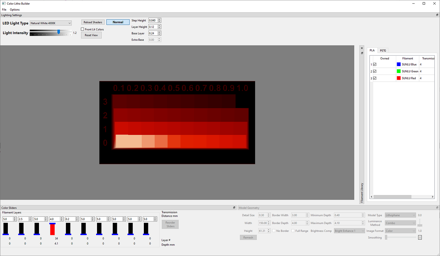
The hardest part of the process is to know your filament well enough to characterize it in HueForge. Included with every copy is a Filament Transmissivity Grid that I use to measure that, and you can load into HueForge and adjust color and Transmissivity values to compare.
Mostly you will be looking at the lower rows of the model to see if they match.
If anything, it looks like this filament (Eryone Red PETG) is MORE transmissive that I’ve set it to be.
So I’ve gone from 4 to 6 and it looks a lot closer. There are other variables, but this process will help you dial in your filaments and get them well represented in HueForge. And as the community does that work, we will build up a large library of filaments with known parameters that can be shared.
I hope this was interesting. If it was and you aren’t subscribed, consider subscribing. If you think someone else should see this, please consider sharing it with them.









Very cool, nicely made!